READING 17 · HOW IT BREAKS · PAST ULTIMATE
Brittle Fracture
No stretch, no warning, no second act. What changes a material from ductile to brittle, the flat bright surface with its chevron markings pointing home, and the historical failures that made the mechanism famous.
§ 01The break that gives no warning
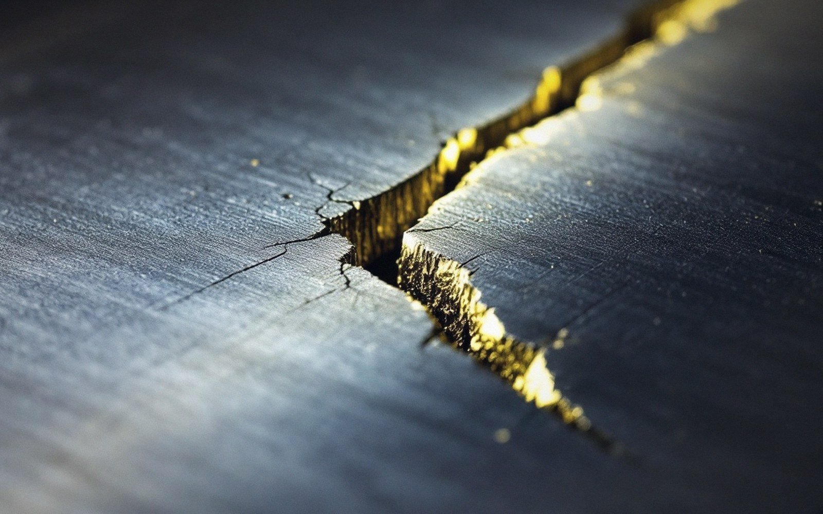
A ductile failure is almost legible. The material stretches, thins at the neck, and the change in shape tells an observer that something is happening and that it has been happening for a while. A brittle fracture does none of that. The two faces of the break are nearly mirror images of each other, flat and bright, fitting together like a puzzle because almost nothing moved before separation. The crack ran faster than any intervention could have followed — in steel, a brittle crack can propagate at speeds approaching a kilometre per second — and the energy it consumed was tiny compared to the stored elastic energy that drove it.
That is the first thing to understand about brittle fracture: it is not a particularly large load doing something dramatic to a weak piece of material. It is a crack-tip mechanism, and the load doing the driving may be entirely within the design envelope. The structural engineer who sized the section was not necessarily wrong. The failure mode simply was not the one the design assumed.
The Charpy impact test exists to characterise this transition
§ 02What shifts a material from ductile to brittle
Steel is the canonical example, and the shift is temperature-dependent. At room temperature, mild steel pulled in a tensile test gives a familiar S-shaped stress–strain curve, with a generous plateau of plastic deformation before fracture. Cool the same steel and test it again. Below a certain range — the ductile-to-brittle transition temperature — the plateau disappears. The material reaches a critical stress, a crack runs, and the test bar separates with almost no plastic work done. The transition is not a sharp line but a range that varies with the specific steel: its carbon content, grain size, and whether its processing history has introduced embrittling inclusions.
The Charpy impact test exists to characterise this transition. A notched specimen is struck by a swinging hammer, and the energy absorbed in fracture is measured from the difference in the hammer's height before and after the blow. Plot absorbed energy against temperature and the result is a sigmoidal curve, dropping from a tough upper shelf to a brittle lower shelf over a range that can span tens of degrees. The test is deliberately severe — the notch concentrates stress, the impact rate is high — but that severity is intentional. It surfaces a susceptibility that slower, smoother loading might never trigger, and it gives designers a temperature below which that material in that condition should not be trusted at the design load.
Thickness matters too, and this catches people out. A thin plate loaded in tension has relatively free surfaces and can yield in those through-thickness directions; the material at the crack tip is in a state of plane stress, and it can do plastic work. Thicken the plate and the interior is now constrained by material on either side: it cannot yield freely, and the crack-tip state shifts toward plane strain. Under plane strain, the critical stress intensity for crack extension — the fracture toughness, expressed as K_Ic — is lower than you would infer from tests on thin material, which is why fracture toughness values taken from thin specimens can be misleadingly optimistic for heavy section applications.
Geometry is the third driver. Any feature that concentrates stress — a sharp notch, an angular weld toe, a drilled hole with a small fillet, even a stamped identification mark — is a pre-existing stress raiser. The nominal stress in the section may be unremarkable; the local stress at the root of the notch is a multiple of it, and if that multiple is large enough and the temperature is low enough and the strain rate is high enough, the conditions for brittle initiation are met. The three factors — temperature, thickness and geometry — do not act independently. Each pushes the material toward the brittle regime; when all three combine, the result can surprise designers who considered each one in isolation and judged each one acceptable.
The diagnostic triad
- Ductile-to-brittle transition temperaturethe temperature range below which absorbed fracture energy drops sharply; varies with steel composition and processing
- Plane stress vs. plane strainthin sections have more freedom to yield at the crack tip (plane stress); thick sections constrain the tip (plane strain), giving lower apparent toughness
- Notch sensitivitythe amplification of local stress by geometric features; a sharp re-entrant angle or weld root concentrating stress beyond what nominal calculations show
§ 03The fracture surface and what it records
A brittle fracture surface has a characteristic appearance that allows a fractographer to work backwards to the origin. The surface is granular and flat — in a transgranular cleavage fracture it has a faceted brightness from the crack plane following crystallographic directions grain by grain — and it carries chevron markings, river marks, that converge on the initiation site. The chevrons are the traces of crack-front segments that were running on slightly different planes and periodically linking; they point upstream, toward where it started.
At the initiation site there is often something to find: a weld root lacking fusion, a heat-affected zone with a coarse grain structure from too much thermal input, a small pre-existing crack. In engineering failures, the initiation site is almost always a geometric or metallurgical stress raiser. The background load that drove it is rarely extraordinary; the combination of the ordinary load with the local stress concentration and the insufficient toughness is what crossed the threshold.
The flat bright faces are also diagnostic in a negative sense: almost no shear lip, the angled band of ductile fracture that forms at the free surface as the final ligament tears. A heavily shear-lipped fracture is a different story, one with significant plastic work. A brittle fracture face with a thin shear lip only at the very edges is telling you that the material ahead of the main crack front did essentially nothing before the crack arrived and the whole thing was over.
Historical turning points
- Schenectady fracture, January 1943a Liberty ship hull fractured at dockside in calm water; part of a cluster of brittle fractures that drove revision of steel specifications and weld detail practice
- Liberty ship programmelinked continuously-welded construction to crack propagation without arrest; prompted development of Charpy toughness requirements in structural steel specifications
- Mid-twentieth-century pressure vessel failuresestablished the role of section thickness in shifting the fracture regime; informed explicit toughness requirements in ASME and BS pressure vessel codes
§ 04The failures that changed the understanding
The Liberty ship fractures of the 1940s are the defining case. Several hundred of these mass-produced welded cargo ships developed cracks in service, some catastrophic and near-instantaneous; a handful broke completely in two, including the Schenectady, which fractured at a dockside in calm water in January 1943. The investigation found the same combination every time: steel that by contemporary specifications was entirely acceptable but that had a high ductile-to-brittle transition temperature, notch-introducing weld details such as square-cut hatch corners, and service in the cold waters of the North Atlantic and Arctic.
The contribution to understanding was considerable. Welded construction, unlike riveted construction, creates a continuous structure in which a crack is not arrested when it reaches a plate boundary — there is no boundary. A riveted hull has natural crack-arrest features built in; a continuously welded hull does not unless it is designed with them. The Liberty ship programme drove research into notch toughness testing, led directly to the specification of Charpy requirements for structural steels used in low-temperature service, and eventually contributed to the development of fracture mechanics as a formal engineering discipline.
The second great historical cluster is the series of pressure vessel and storage tank failures in the mid-twentieth century that pointed to the same mechanism operating in thicker sections. Each failure refined understanding of how thickness shifts the fracture toughness regime, and each one pushed the standards — ASME, BS, and their equivalents — toward explicit fracture toughness requirements rather than the implicit faith in yield strength that had characterised earlier codes.
How the surface speaks
- Chevron / river marksfractographic features pointing toward the crack origin; allow initiation site identification
- Granular bright facecleavage fracture following crystallographic planes grain by grain; contrasts with the silky grey of a ductile fibrous fracture
- Shear lipthe angled ductile band at free surfaces; its absence or thinness confirms predominantly brittle behaviour
§ 05What a margin against yield does not provide
The deepest practical lesson is the one that most unsettles structural intuition. A safety factor against yield is not a safety factor against brittle fracture. A section that is stressed to half its yield stress is under no plastic threat at that load, but if it contains a sharp enough crack in a material of low enough toughness at a temperature below the transition range, the section may fracture before yielding ever occurs. The nominal working load is in the safe zone by the metric the designer used, and the failure happens anyway.
Fracture mechanics addresses this by characterising the flaw size and the toughness together: K_Ic, the critical stress intensity factor, connects crack geometry, applied stress and the point at which unstable crack extension begins. Specifying a minimum toughness, mandating inspection to ensure flaws stay below a limiting size, and choosing materials whose transition temperature lies well below the lowest service temperature — these are the three levers. They are not interchangeable: a high-toughness material cannot fully substitute for inadequate inspection, and inspection cannot substitute for toughness in a part that operates below its transition temperature.
The bright flat fracture surface is a record of a failure that happened before the structure knew it was in trouble. That is the feature that distinguishes it from every mode involving slow growth or visible deformation: it was already over when the noise was heard.